Following a line with a camera
The Color Sensor works well enough for following lines, but it can only see where the line currently is, and only if it is nearby.
With a camera, you can look ahead and see the upcoming curve. In this chapter you’ll make a line follower robot with your camera as shown below.
Using smart sensors: Be sure to check out the smart sensors introductory guide first. Once you know how to connect your phone and receive values, you’re ready to run the example below.
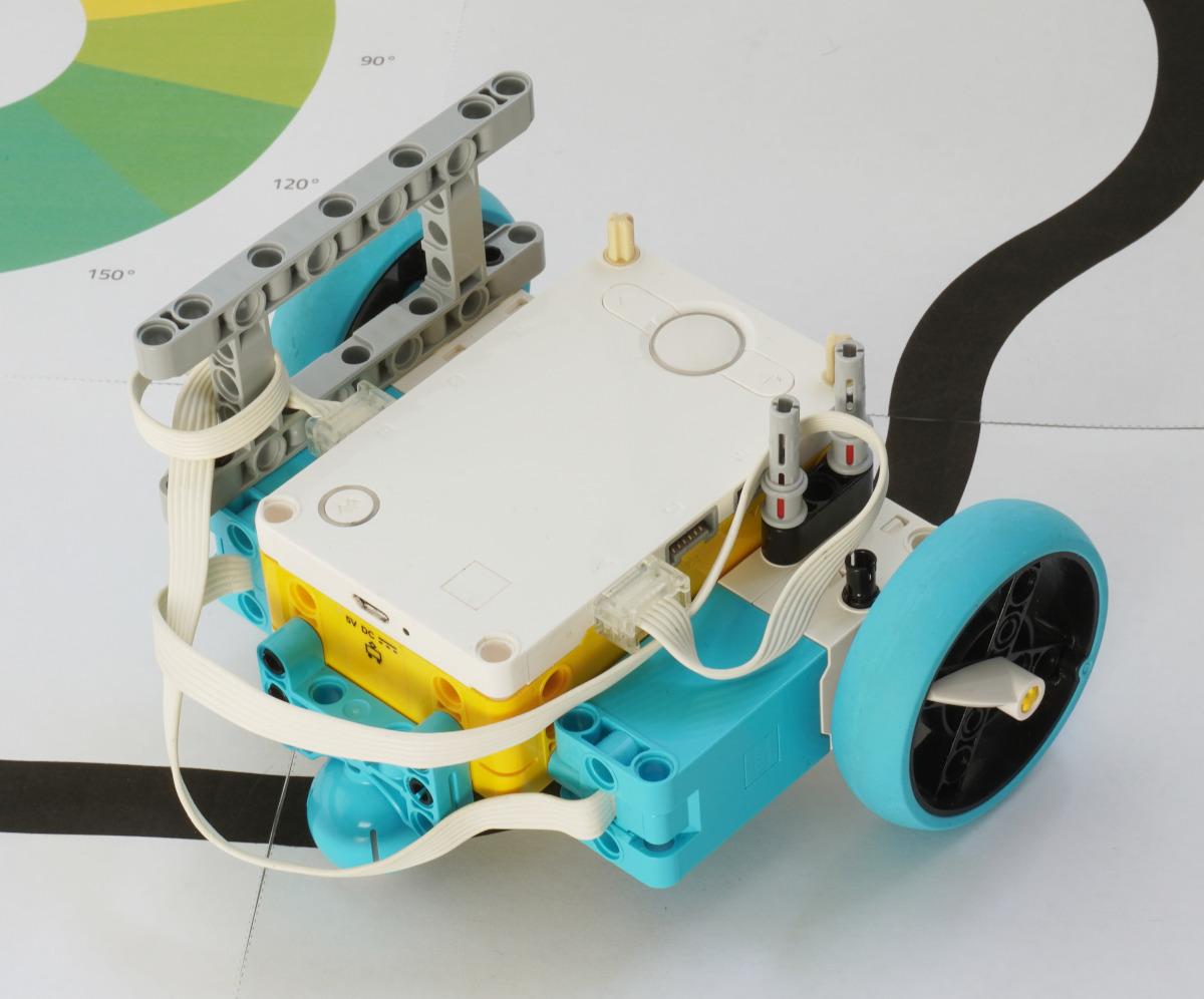
Building a robot
Modern phones are quite big, so you’ll have to experiment with what works best for yours. I ended up building a robot that is mostly flat, so the phone can rest directly on it with the camera facing down. You can see this design below.
You can experiment with different built-in cameras using the camera icon in the top right of the Pybricks camera view. You could try the wide angle lens, for example.
Line position and angle
This smart sensor returns two values:
- 0: The average horizontal position of the line with respect to the middle. 100% means it is all the way right; -100% is all the way left; 0% is the middle.
- 1: The approximate angle of the line. 90 degrees is to the right; -90 is to the left; and 0 is straight ahead.
The position tells you something about where the line is right now. The angle is an indicator of where the line is going as you drive. You can use these for various line following strategies.
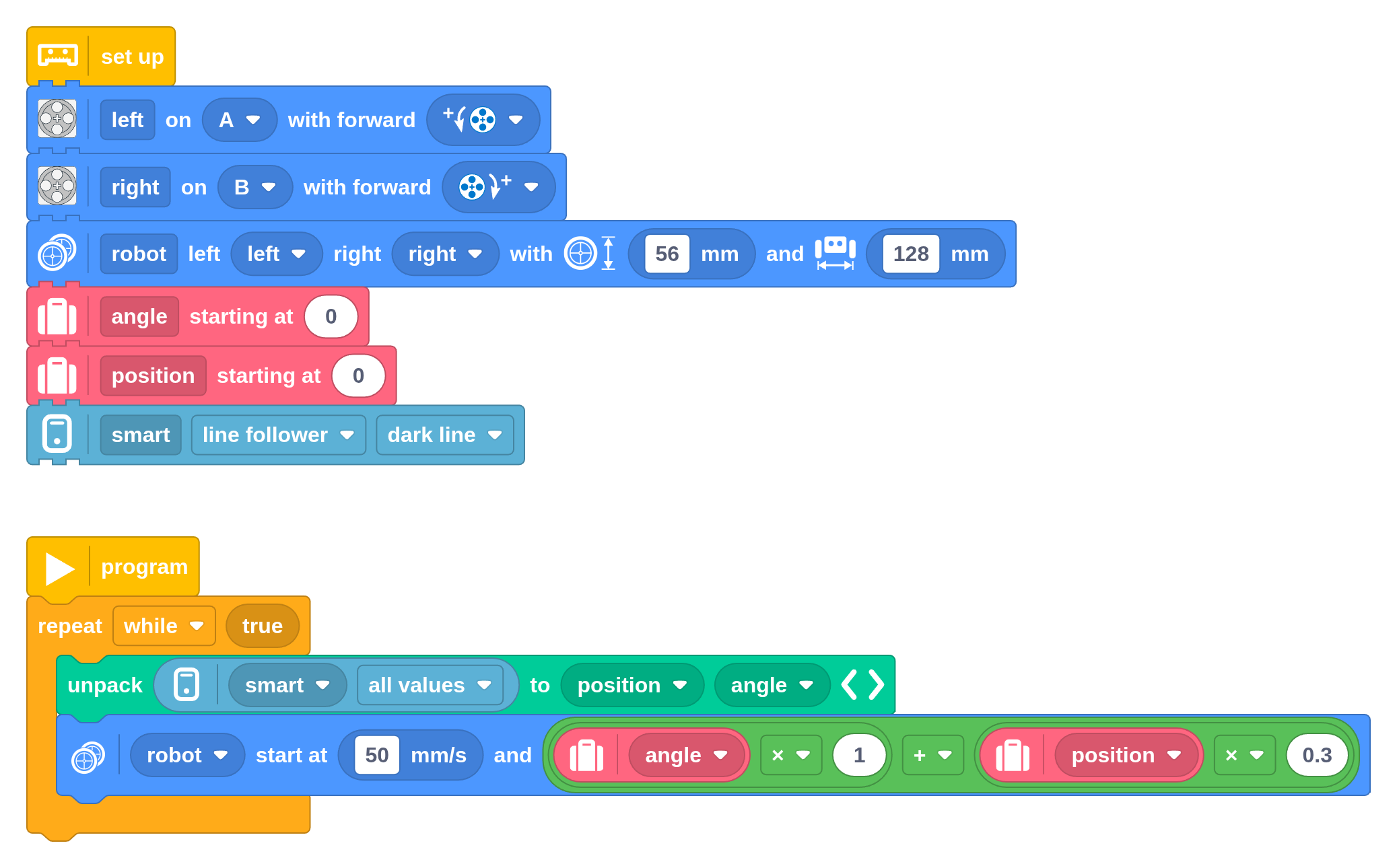
In this example, we use a weighted sum of both. This means it will steer towards the line using the position correction, and also in the direction of the line using the angle correction.
You can tweak the scaling values to see what works best for your design. What happens if you use only one or the other? Which is the most important value, and why?
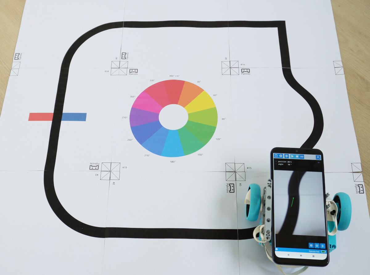
Printing a line track
You can print your very own track with this PDF file. Just cut out the squares along the dotted lines and tape them together.
Most printers let you choose which pages to print, and how many of each. To print the track in this picture, for example, enter:
2, 2, 3, 3, 3, 14, 18, 19
Improving speed
On my budget phone, the number of frames processed every second is relatively low. Try experimenting with different phones to see differences in performance. You can also connect with USB to reduce the latency of the messages to the robot. Then you should be able to drive faster without losing the line.
Using Python (optional)
If you prefer to use Python, you can use the following example as a starting point. It’s the same as the block program above.
from pybricks.messaging import AppData
from pybricks.parameters import Direction, Port
from pybricks.pupdevices import Motor
from pybricks.robotics import DriveBase
from ustruct import unpack

# Set up.
left = Motor(Port.A, Direction.COUNTERCLOCKWISE)
right = Motor(Port.B, Direction.CLOCKWISE)
robot = DriveBase(left, right, 56, 128)
angle = 0
position = 0
app = AppData([(3, 2)])
app.configure(3, 0, bytes([0]))


# The main program starts here.
while True:
    position, angle = unpack('bb', app.get_bytes(3)) or [0] * 2
    robot.drive(50, angle * 1 + position * 0.3)