Basic robot navigation
Now that you’ve built a robot and made some basic programs, let’s have a closer look at how you can make the robot move effectively.
Throughout this chapter, we’ll use the angle sensors built into the motors to drive straight and turn. It’s important to have a good understanding of basic driving and navigation before trying out the gyroscope in later chapters.
You’ll learn to use each of the following blocks:
By a given distance, turn angle, or forever.
like speed and acceleration
Driving with two wheels
A typical LEGO robot drives using two wheels, each powered by one motor. A passive support wheel or ball caster prevents it from tipping over. The robot drives straight ahead by turning both wheels at the same speed. It turns by making one wheel go at a different speed or in the opposite direction, as pictured below.
wheel
wheel
Wheel diameter and base width
You can tell your robot to drive a given distance or turn by a given angle. The robot works out how much it needs to move each wheel to get there. To calculate this, it needs to know the wheel diameter and the wheelbase or track, as shown below.
diameter
To measure the wheel diameter, place your ruler on the wheel. It is the distance from one end of the rim all the way to the other end. To measure the wheelbase, place your robot on top of the ruler and note the distance between the points where the wheels touch the ruler.
On my robot, I measured 56 millimeters for the wheel diameter and 128 for the wheelbase. What did you measure?
Tip — One LEGO unit is exactly 8 millimeters. A LEGO unit is the distance between two holes or studs. In this example, the wheel diameter is the same as a length-7 beam. And 7 × 8 makes 56 mm! Similarly, the distance between the wheel contacts is 16 LEGO units, and 16 × 8 is 128 mm. Use a ruler for more precision!
Basic lines and turns
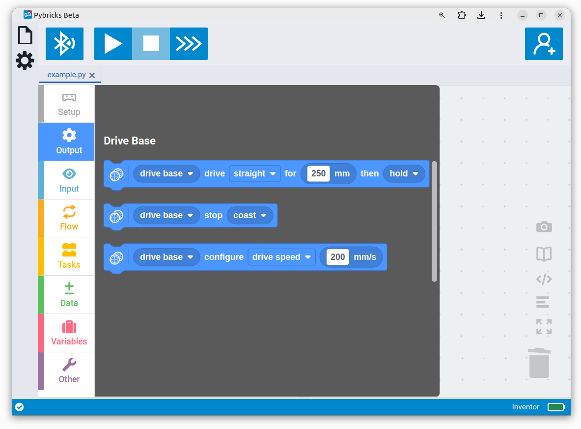
You enter your measured values in the Drive Base Setup block. Now add three Drive blocks to make it move. Create the program as shown below. Run the program when you’re ready.
Your robot should now drive forward for 250 mm (25 cm, or about 10”), turn around, and drive back to where it started.
Challenge #3.3.A: Square it ⸺ Can you make your robot drive in a square? How many Drive blocks do you need to do it? When you’re ready, change the program to a rectangle that is 250 mm by 1000 mm. When it drives, place an object at each of the corners as it passes by. Verify your results with a measuring tape.
Challenge #3.3.B: Hexagons are the bestagons ⸺ Modify your solution from challenge 3.3.A to drive in a hexagonal shape instead. How many degrees should each turn be? How many blocks do you need this time? Discuss ⸺ Draw the shape that the robot drives on paper and mark the angles that the robot makes. What do you get if you add up the angles of all turns? Do it for the square from challenge 3.3.A too. Do you notice anything? Is this also true for triangles and pentagons? Are there shapes where this does not apply?
Challenge #3.3.C: Robomenu ⸺ Have the robot drive around in the shape of letters to spell out your favorite food. Can your classmate guess what you wrote?
Working with millimeters (mm) may appear awkward at first, especially if you are used to thinking in centimeters (cm) or inches (“). Instead of converting every number in your head or using a calculator, we recommend playing with millimeter values to become familiar with them. Try things out, get it wrong, and then fix it. It’s a useful skill to have. The following table helps place common numbers in the context of everyday objects and values. The rightmost columns are only there to help you the first time. Try to think in millimeters directly: Go from drive along my desk to drive about 600mm without converting. Then try it!
| mm | Intuitive examples | cm | m | imperial |
|---|---|---|---|---|
| 1 | a pencil stroke, fingernail, paperclip | 0.1 | 0.001 | ~0.04 in |
| 10 | a small LEGO brick, a small marble | 1 | 0.01 | ~0.40 in |
| 100 | a playing card, a large apple, a small phone | 10 | 0.01 | ~4 in |
| 250 | letter paper, a ruler, a small notebook | 25 | 0.25 | ~10 in |
| 500 | half a meter, half a yard, a small step | 50 | 0.5 | ~1 ½ ft |
| 1000 | a meter, a yard, a big step | 100 | 1 | ~3.3 ft |
| 10000 | a classroom | 1000 | 10 | ~33 ft |
Verifying and adjusting the dimensions
In practice, wheels compress slightly under the weight of your robot, especially with soft rubber tires. To verify, program a single movement to drive 1000 mm. Measure how far it really traveled with a measuring tape. Compensate as follows:
- If your robot does not drive far enough, decrease the wheel diameter value slightly.
- If your robot drives too far, increase the wheel diameter value slightly.
If you run the program again, the robot should be closer to 1000 mm this time. Adjust again as needed.
Motor shafts and axles can bend slightly under the load of the robot, causing the ground contact points to shift slightly. To verify, make your robot turn 360 degrees and check that it is back in the same place.
- If your robot does not turn enough, increase the wheelbase value slightly.
- If your robot turns too far, decrease the wheelbase value slightly.
If your results are inconsistent, avoid tweaking these numbers endlessly. The cause might be elsewhere, such as in grip or the robot design. For example, make sure that the wheels don’t slip. After all, the robot only knows how far the wheels turn, not how far it really drives.
Making curves
Note ⸺ This feature changed recently. Since v3.6.1 (Pybricks Code v2.6.0), it works as documented below. If you made code with earlier versions, your code will continue to work unchanged. The old Drive block curve method works just like before, but it displays a ⚠-icon to remind you to get a new block from the palette. Once you do, it will use the new behavior. What changed? The definition of driving backwards is more logical now, and we added the veer option for slight turns.
Your robot can also drive along a curve. This is a portion of a circle. A single curve is sometimes faster than a combination of straights and turns.
positive distance/angle
positive distance/angle
negative distance/angle
negative distance/angle
You choose the size of the circle by setting the radius. A big value means a big circle with a wide turn. A small value is a tight turn. The value cannot be zero. To turn in place, just use the simpler turn method we used earlier.
Choose a positive radius value to drive along a circle on the robot’s right. Choose a negative radius for a circle on the left, as shown above. Next, choose how far you want to drive along the circle. Choose a positive value for forwards along your chosen circle. Choose negative for reverse.
With the curve option, you choose how far to drive as an angle. With the veer option you specify how far to drive as a distance. This can be useful for driving almost straight but deliberately veering in one direction.
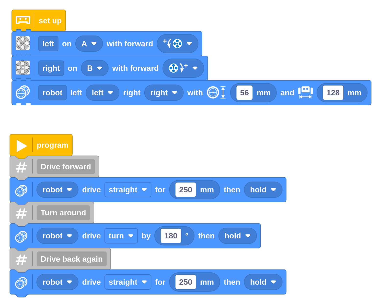
To practice making curves, create the following program that makes your robot drive in an oval and stop where it started. Try the veer option too.
Challenge #3.3.D: Squaring the circle ⸺ In Challenge #3.3.A, you made a program to drive in a square with four straights and four turns. Can you adapt it to replace two straights and a turn with a single curve? The resulting shape should be a quarter of a pizza. What do the radius and angle need to be for the curve? Draw it on paper first and mark the straights, turns, and the curve with the right parameters.
Challenge #3.3.E: Spiralling ⸺ Can you combine multiple curves to drive in a pattern that spirals outward? Start by driving in half circles, each with a bigger radius than the last. Discuss ⸺ Is this a real spiral shape? If not, what could you change to make it more like a real spiral?
Adjusting speed and acceleration
In your previous programs, the robot was driving at the default speed, which is relatively slow. You can change how fast the robot drives and turns with the Drive Base Configuration block.
Throughout these examples, the Configuration Block is used several times with different values. For most robots, a single set of values is sufficient. You could put them all at the start of your program for clarity.
Drive speed and acceleration
The drive speed is measured in millimeters-per-second, or mm/s. It is the distance that the robot travels (in mm) in one second. For example, if the robot drives 500 mm in 2 seconds, its speed is 500 / 2 = 250 mm/s. The robot determines how fast to rotate the wheels based on the wheel diameter setting.
Drive acceleration is the change of the speed value, every second. So it is the change of the millimeter-per-second speed, per second. This is often written as mm/s/s or mm/s². To reach a top speed of 250 mm/s in half a second, the acceleration should be 250 / 0.5 = 500 mm/s².
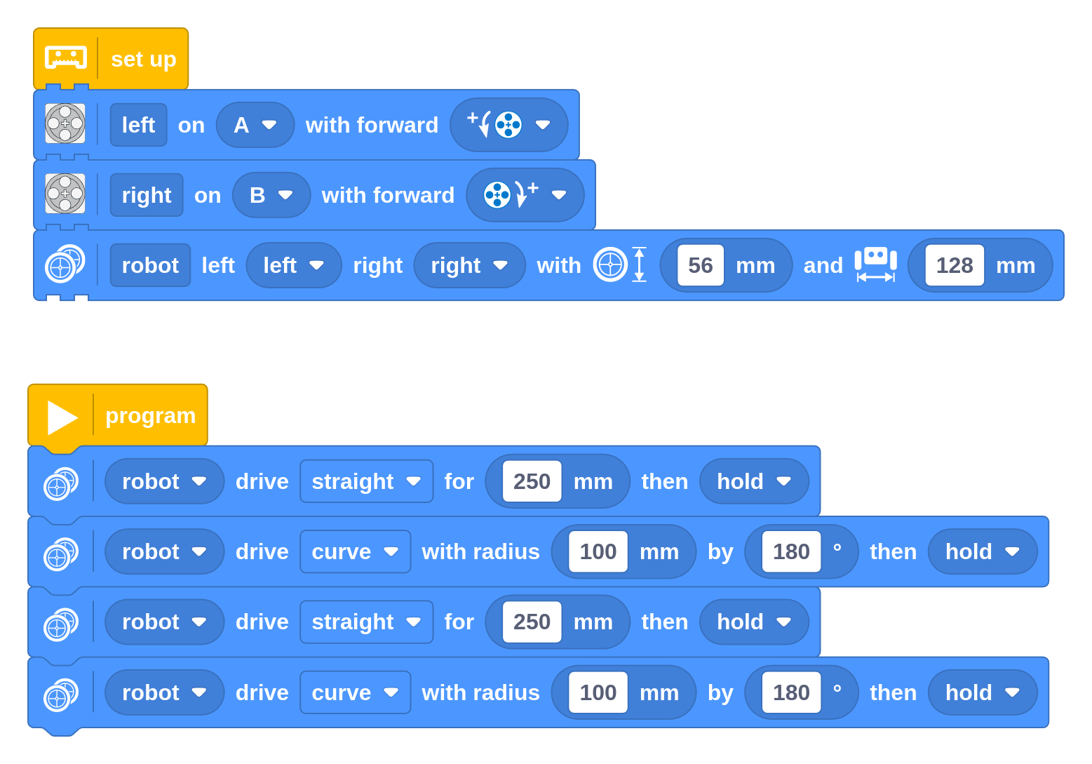
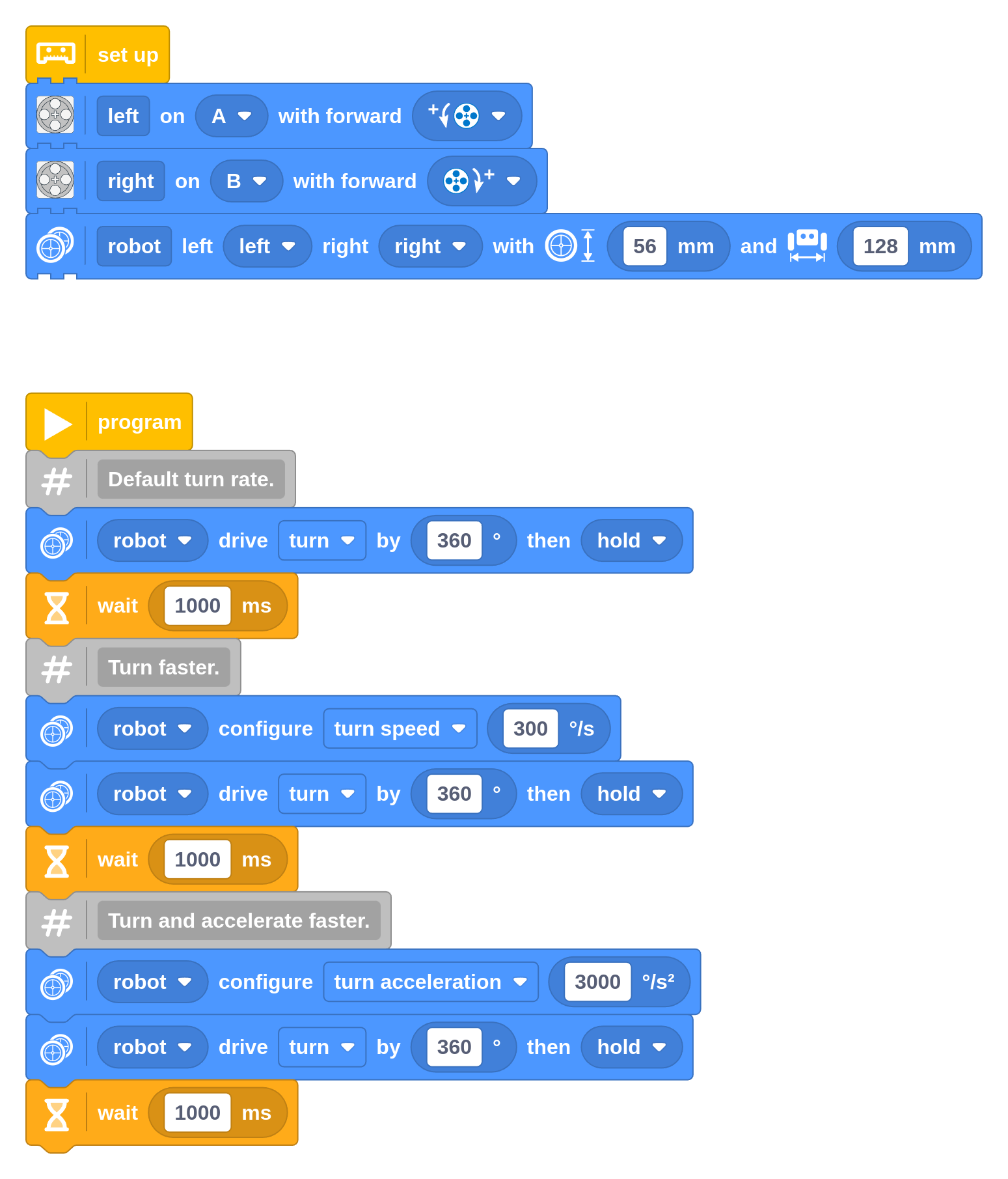
The following example shows how you can change speed and acceleration. It drives the robot back and forth with different speed and acceleration values.
Challenge #3.3.F: Speed ticket ⸺ Can you verify the speed value with an
experiment? Make a program with one Configuration block and one block to
drive straight for 10 meters (10000 mm). Verify that it drives the required
distance, and measure the duration with the stopwatch on your phone. Calculate
the speed as 10000 / T, where T is the measured time in seconds. Does
your result match the speed setting? Discuss ⸺ You set the speed but don’t
tell your friend what you chose. How close can your friend get by measuring it
experimentally? Do you get similar values every time? How can you
make the test more accurate? Why is it helpful to drive such a long distance?
Does acceleration play a role?
Turn speed and acceleration
The turn speed (or turn rate) is measured in degrees per second, or deg/s. It is the angle that the robot makes when viewed from the top, in one second. For example, if the robot turns 180 degrees in 2 seconds, its speed is 180 / 2 = 90 deg/s. The robot determines how fast to rotate the wheels based on wheel diameter and wheelbase settings.
Turn acceleration is the change of the turn rate value, every second. So it is the change of the degrees-per-second rate, per second. This is often written as deg/s/s or deg/s². To reach a top turn rate of 90 deg/s in half a second, the acceleration should be 90 / 0.5 = 180 deg/s².
The following example shows how you can change the turn rate and acceleration. If all works well, it should make three perfect rotations. In practice, you might find that the wheels slip a bit more in the final fast turn, especially if the wheels are a bit dusty.
Maximum speed and acceleration
The maximum drive and turn speed of your robot depend on your design. You can drive faster with big wheels than with small wheels. After all, you can turn faster with a smaller wheelbase than with a wide wheelbase.
SPIKE motors can turn up to about 1000 degrees per second when there isn’t much load. With 56 mm diameter wheels, the maximum speed is therefore about 1000 / 360 × 56 × π ≈ 488 mm/s.
If you try to set a much higher value, you’ll see an error that you’ve provided an invalid argument. This helps prevent you from trying arbitrarily large values that don’t actually do anything.
This may seem a bit complicated at first. However, specifying a value that you can measure and verify is much more reliable compared to choosing an arbitrary percentage (0–100%).
We recommend staying away from the absolute limit. Near the limit there is less room for the robot to self-correct if it slides or encounters obstacles.
Challenge #3.3.G: On the limit ⸺ Create a program that has the robot drive back and forth at high speed. Determine which acceleration values your robot can still handle without slipping. What happens if you put a bit of dust on your wheels?
Challenge #3.3.H: Snail’s pace ⸺ Experiment with low speed values and low accelerations. Discuss ⸺ Is going slower always better? Is there also a lower speed limit where accuracy becomes an issue? What is the role of friction at low speeds? Research ⸺ Look up stick–slip motion. How does it apply here?
For very short moves, the robot may not always reach the configured speed since it has to slow down in time to stop precisely on target. So the drive and turn speed settings are more like speed limits that it will reach when possible.
The acceleration setting controls both the acceleration at the start of a move and the deceleration at the end. To control them separately, you can provide a list with two values. This technique is not covered here.
Speed and acceleration in curves
Curves combine driving and turning. You can adjust the settings in the same way as above. The robot will automatically select the setting that best applies to your move.
What does this mean? A tight curve is quite similar to a plain turn, so the robot mostly uses your chosen turn speed and acceleration, ignoring the drive speed limits. For a wide curve with a long distance, the robot will use your drive speed and acceleration settings and ignore your turn settings.
Understanding stop modes
For each straight, turn, or curve, the robot comes to a controlled stop when it reaches its target. Then your program proceeds with the next block. If that block does nothing with motors, what should the motors do in the meantime? That’s what the final setting on the Drive block is for.
The robot drives by a given amount and then coasts, brakes, or holds the motors. We’ll tell you what that means, but it is better to experience it yourself using the following program. After each move, try twisting the wheels manually and see what happens. Repeat the program if you need to.
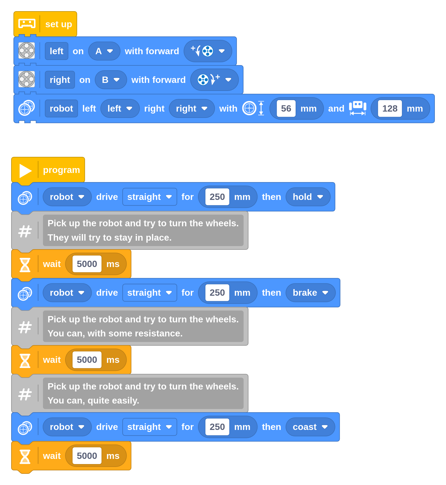
With hold, the robot will keep holding the wheels in place, even if you try to turn them. With brake, the motor uses the electricity generated by your movement to slow it down. With coast, it’s as if the motor is disconnected: it spins freely except for friction.
With brake and coast, the wheels can turn a bit between subsequent commands. Over time, this can make your robot less accurate. For example, if you told it to turn 90 degrees but it ended up doing 91, the next time you tell it to turn 90 degrees it will aim at 181, and possibly reach 183. This adds up.
With hold, the wheels are held in place between moves. Even if it didn’t perfectly reach 90 degrees the first time, it will still aim for 180 the next time, since it can assume that you didn’t intend to move the wheels.
Combine movements without stopping
Instead of choosing one of the stop modes, you can choose continue moving. When you do, the robot won’t decelerate as it approaches the block’s destination like it normally does. Instead, it will keep going. This means the robot is still at speed when it begins to execute the next block. So the next command does not have to accelerate either and just keeps going. It’s as if sequential moves are blended together.
Try it out by modifying the program for the oval you made earlier. It should complete the oval much more quickly since it does not have to stop and accelerate four times.
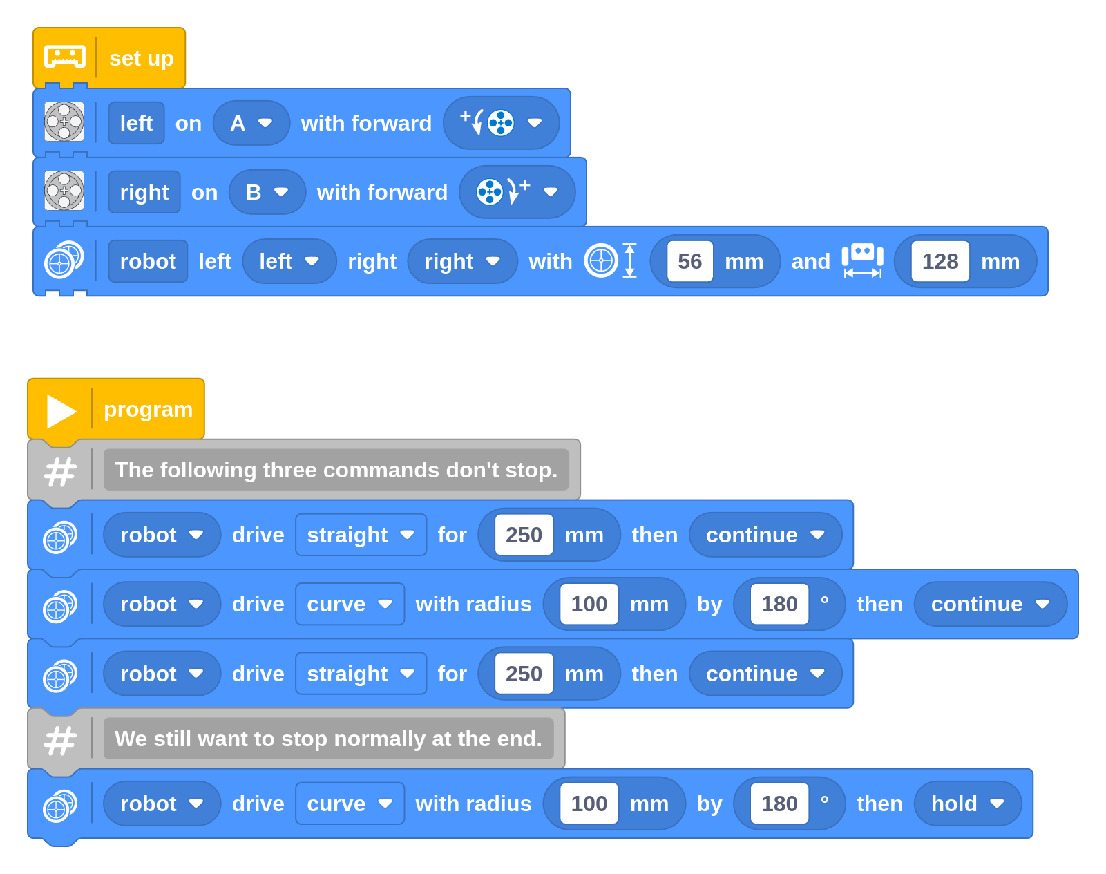
If you use a sequence of movements like this, be sure to have the final block stop using one of the stop modes as shown above. Otherwise, it would just keep driving forever until you use another block to stop it.
Using continue is mainly useful to combine straights with larger curves. Going at full speed into a tight or in-place turn is not a good idea, as the wheels must suddenly slow down, causing them to slip.
Drive forever (until you change course)
So far, each Drive block completed when your chosen distance or turn angle was reached. In many cases, the exact distance is unknown in advance. For example, you might want to keep driving until you detect an obstacle, whenever that is.
This is where the forever mode of the Drive block comes in, as shown in the following example. Instead of a distance or turn angle, you choose the drive speed (mm/s) and turn rate (deg/s) that it should maintain “forever”. That is, until you tell it to do something else or the program ends.
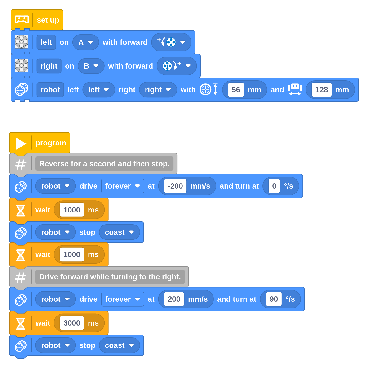
In this example, the robot keeps driving as it continues with the next blocks in your program. In this case, those include a Wait Time block to pause the program for a second and then a Stop block to stop driving. Then it starts another move. In the Stop block, you can choose one of the three stop modes, which work the same as discussed for other movements earlier.
In the next chapters, you’ll use this technique to wait for a certain sensor value to be reached, instead of waiting a fixed number of seconds.
Don’t forget the mechanics
When your robot doesn’t quite move like it should, it’s not always a coding issue. Your robot design is really important too!
Iterate with your design as much as with your code. If something doesn’t work, document it with pictures, videos, and notes about why it didn’t work. Don’t be scared to take things apart! Take pictures as you disassemble it. You can always view them in reverse if you want to rebuild your previous design.
Challenge #3.3.I: What’s in a diameter? ⸺ Given a target distance of 1000 mm, can you work out how far both wheels need to turn to get there? Write down your estimate. Try it out with a small program, and count the number of revolutions of the white marker on the wheel. Did you get it right? Discuss ⸺ Why does the robot need to know what the wheel diameter and wheelbase are? What happens if you make one value way too small or way too big? What if you use bigger wheels?
Challenge #3.3.J: Turning point ⸺ A conventional car is quite different from your LEGO robot. It drives using an engine or motors and it steers by turning the front wheels. Can you draw a top-view diagram like the one above, but for a car? Be sure to draw exactly how the front wheels are positioned and add arrows to indicate the direction of travel. How is it different from your LEGO robot? Why can a car not turn in place? Is this also true for a 4x4 vehicle? How could you modify a car to turn in place? Discuss ⸺ In your diagram, draw straight lines through the front and rear wheel axles. How many intersections do you get, and what is the meaning of these point(s)? Research ⸺ Search for Ackermann steering geometry. Can you build something like it with LEGO bricks?